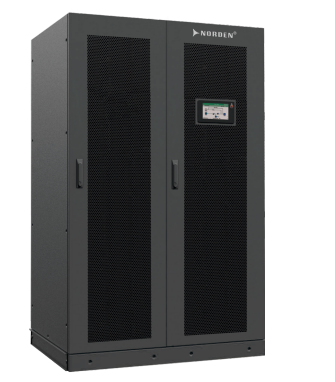


The UPS system is designed with modular architecture, where each module operates independently and contains its own components, including power converters, inverters, and battery systems. This flexible,scalable designs allow for seamless expansion and customized power protection, ensuring continuous operation based on specific need.
The UPS system is designed with modular architecture, where each module operates independently and contains its own components, including power converters, inverters, and battery systems. This flexible,scalable designs allow for seamless expansion and customized power protection, ensuring continuous operation based on specific need.
| PARAMETERS | ||||||
| Cabinet | Cabinet capacity kVA | 100kVA | 150kVA | 200kVA | 300kVA | 400kVA |
| Module capacity kW | 50kW | |||||
| Max. module number | 2 | 3 | 4 | 6 | 8 | |
Input | Normal Voltage | 380/400/415Vac, (3Ph+N+PE) | ||||
| Operating voltage range | 138~305Vac for 40% load; 305~485Vac for 100% load | |||||
| Operating frequency range | 40Hz~70Hz | |||||
| Power factor | >0.99 | |||||
| Harmonic distortion (THDi) | ≤3% (100% linear load) | |||||
| Bypass voltage range | Max. voltage : 220V: +25% (optional+10%, +15%, +20% ); 230V : +20% (optional +10%, +15% ); 240V : +15% (optional +10%) Min. voltage : -45% (optional-10%, -15%, -20%, -30%) | |||||
| Bypass Frequency tracking range | ±10% | |||||
| Power walk in | Support | |||||
| Generator input | Support | |||||
Output | Rated voltage | 380/400/415Vac,(3Ph+N+PE) | ||||
| Power factor | 1 | |||||
| Voltage regulation | ±1% | |||||
| Output frequency Line mode | Synchronize with input, when the input frequency >±10% (±1%/±2%/±4%/±5% optional), output 50/60 (±0.1Hz) | |||||
| Batt. mode | (50/60±0.1%)Hz | |||||
| Crest factor | 3:1
| |||||
| Harmonic distortion (THDv) | ≤1% with linear load; ≤3% with nonlinear load
| |||||
| Efficiency | Up to 96% | |||||
Battery | Battery voltage VRLA Battery | 360Vdc~600Vdc (30~50 pcs, 36 pcs default, 36~50 pcs no power derating; 32~34 pcs output power factor 0.9; 30 pcs output power factor 0.8) | ||||
| Power module charge current | 20A (Max.) | |||||
System Features | Transfer time | Utility to Battery : 0ms; Utility to Bypass : 0ms | ||||
| Overload Inverter mode | ≤110% 60min, ≤125% 10min, ≤150% 1min, 150% 1.2s shut down inverter | |||||
| Bypass mode | 30°C : 135% for long term; 40C: 125% for long term; >1000%, 100ms | |||||
| Overheat | Line Mode : Switch to Bypass; Backup Mode : Shut down UPS immediately | |||||
| Low battery voltage | Alarm and Switch off | |||||
| Self-diagnostics | Upon Power On and Software Control | |||||
| Backfeed protection | Support | |||||
| Battery | Advanced battery management | |||||
| Noise suppression | Complies with EN62040-3 | |||||
| Audible&visual alarm | Line Failure, Battery Low, Overload, System Fault | |||||
| Status LED & LCD display | Line Mode, Bypass Mode, Battery Low, Battery Fault, Overload & UPS Fault | |||||
| Reading on the LCD display | Input, Output, Battery, Command, Setting, Maintenance | |||||
| Communication Interface | Rs232, RS485, Parallel, LBS, BMS, Dry contact port, Relay card(optional), SNMP card(optional), Battery temperature sensor(optional) | |||||
Environment | Operating temperature | 0~40°C | ||||
| Storage temperature | -25~55°C | |||||
| Humidity range | 0~95% (Non-condensing) | |||||
| Altitude | <1500m, derating required when >1500m | |||||
| Noise level | <73dB | |||||
| Physical | Dimension WxDxH (mm) UPS cabinet(S/F) | 600×850×2000 | 600×850×2000 | 600×850×2000 | 1200×850×2000 | 1200×850×2000 |
| Power Module | 440×620×130 | |||||
Net Weight (kg UPS cabinet | 240 | 260 | 290 | 480 | 540 | |
| Power Module | 34 | |||||
Standards | Safety | IEC/EN62040-1, IEC/EN62477-1
| ||||
| EMC | IEC/EN62040-2 (IEC61000-2-2, IEC61000-4-2, IEC61000-4-3, IEC61000-4-4, IEC61000-4-5, IEC61000-4-6,
IEC61000-4-8, IEC61000-4-11 | |||||


